
Attiny85 Meet Android Doll
Nothing like a fun project with your kids, which can also teach them something about electronics. Or maybe you are someone that just want to use an IC like the ATTiny but looking for a reason to use it. I think this project is fun for all ages and because it is easy to do and build results will show up fast.
So, I created the 3D design for Android Doll, which you can find it here:
Android Doll
From here I thought, it will be cool to just put LEDs in it that way the kids will think it is cool
(I mean they were already with a ahhh moment when they saw the printout)
So after talking with them, they wanted yellow eyes and red mouth.
But I wanted to do something more, something that will make them think: "You can do that?", so I said to them,
well lets make the mouth LEDs trace each other and will go from right to left (or left to right if that is how you like to think of it :D)
To achieve that i'm using the powerful but yet small Attiny 85 Here is a link to the datasheet if you need it: Atmel Attiny-85
So how to make all of that work?
That is a good question. It is few steps process, but very straight forward.
- Flush your Arduino as a programmer (If you don't have an Arduino, but have a Tiny Programmer you can use that)
- Connect jumper wires from your Arduino to the Attiny that way you can flush your program.
- Write your code
- Test on the breadboard
- Move your breadboard design to a PCB
Flush Your Arduino as a Programmer
I assume that you have an Arduino that you can use (I really hope you own an Arduino, but that is a different topic.) If you go to from the Arduino IDE to File->Example->ArduinoISP you will be able to flush your Arduino as ISP and therefore be able to flush the code to the Attiny In case for some reason you do not have that code, i'm including it below for you to download: ArduinoISP.ino (If downloading rename from txt to ino)
Connect Jumper Wires Between Arduino and Attiny-85
Here is the image of how your jumper wires should look like connecting to your Attiny:
-
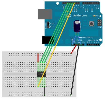
Arduino as ISP to Attiny -
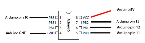
Arduino as ISP to Attiny with Pin Numbers
Writing the Code
The code (If downloading rename from txt to ino) is fairly simple. Each GPIO that is free with the Attiny was related to an LED. Here is a section from the code that declare the GPIO to a friendly name in the code (see picture above for reference):
int rightEye = 1;
int leftMouth = 2;
int middleMouth = 3;
int rightMouth = 4;
Test on the breadboard
When you are done coding and you are ready to test / flash your code to the Attiny, make sure your Arduino IDE is set to use Arduino as the programmer and that you select the Attiny board (You can follow this link that explain how to include Attiny as an option for board selection) By now your breadboard should look something like this:
-
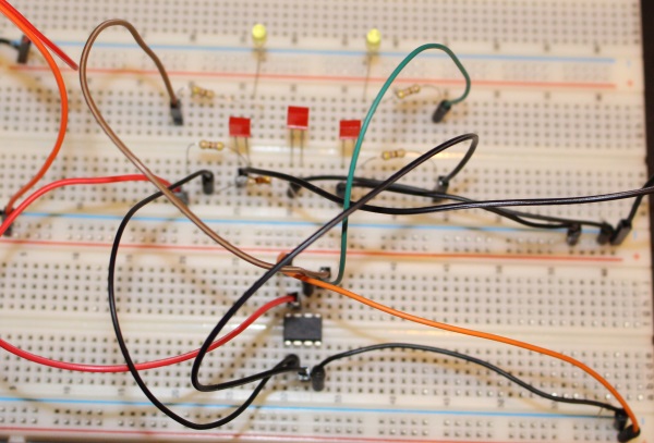
Breadboard Layout
Move your breadboard design to a PCB
This is up to your design skill and likes but here is what I came up with
-
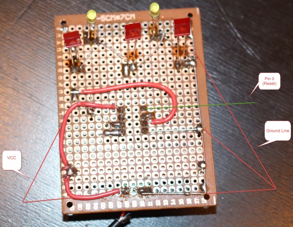
PCB Back -
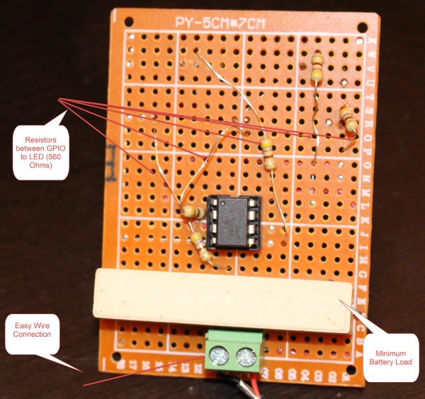
PCB Front
Final Result
-
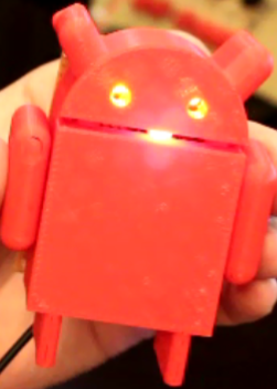
Final Result
This is it. Connect your power to the corresponding rails and enjoy the show. But don't stop there. See how you can change some of the code (make it faster, stronger :D ) or even add that to other projects. For example: I'm thinking that if I connect it with the battery and while my phone is charging, i will show the LED moving. When the phone stopped charging, I will freeze the LEDs that way you have visual indication that the phone is fully charged. Future Project ? Maybe...
If you want to see this in action you can visit the Youtube video here